1.PlaySight volleyball SmartCourt
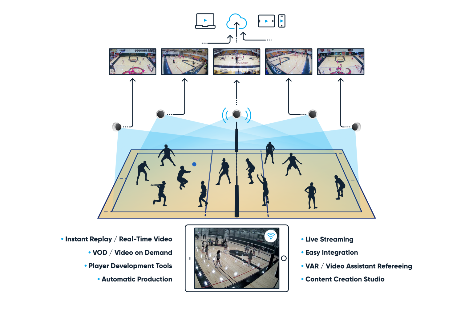 The SmartCourt Play captures everything happening on court with Full-HD video recording, offering instant video review, and live streaming of all practices and matches.
Every SmartCourt is connected to the PlaySight cloud. Once play is complete, all video is automatically uploaded to your account where it’s accessible anytime through playsight.com or the PlaySight app.
Everything is smart, and everything is automatic!
The Full-HD camera:
- POE 1080P camera
- Video compression – H264 (files stored as MP4)
- Mic included, connected directly into the camera (Audio: AAC)
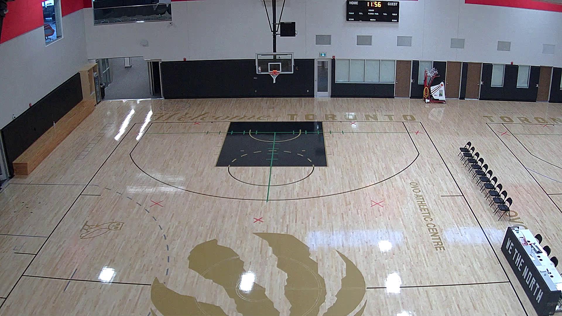
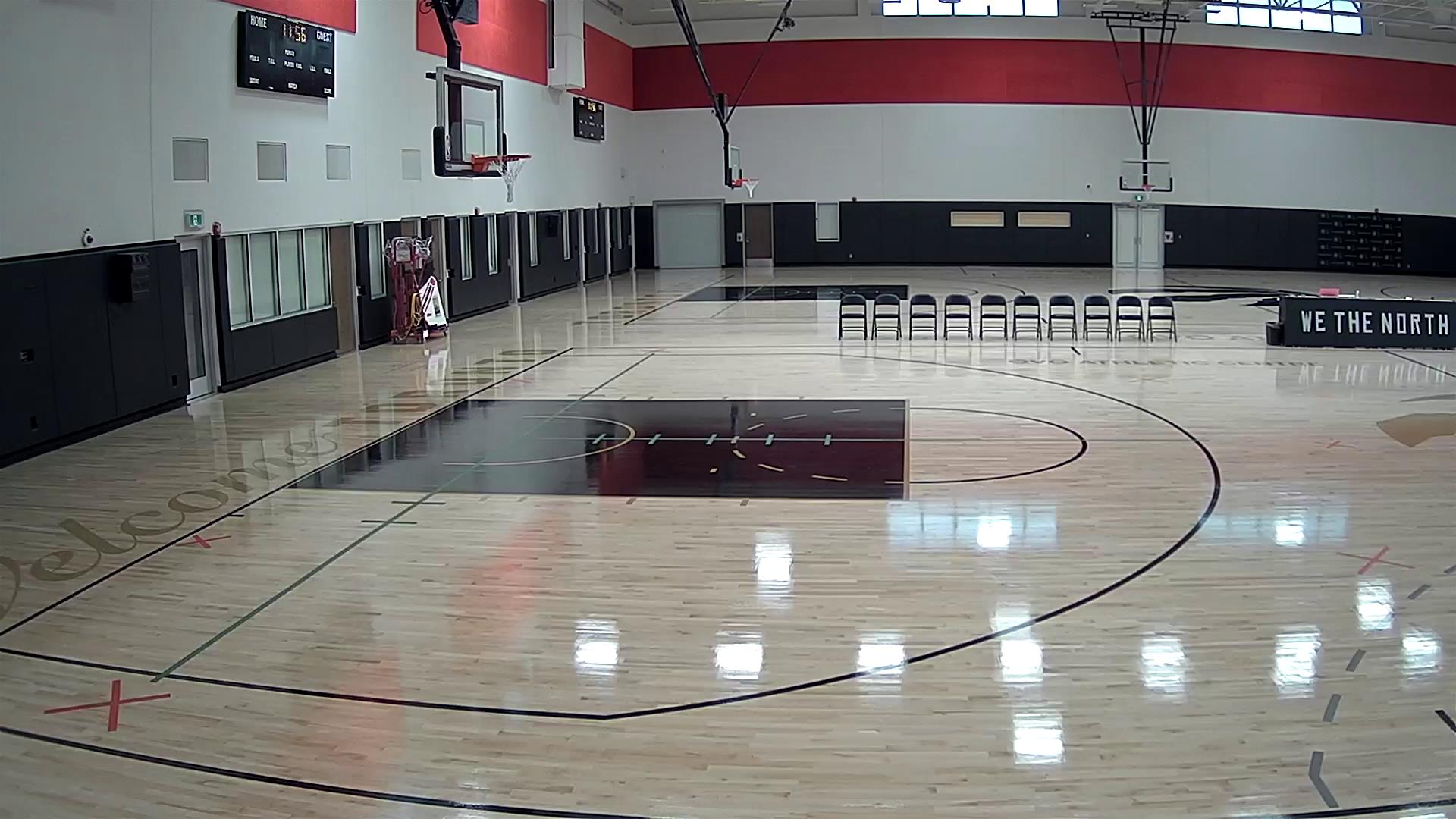
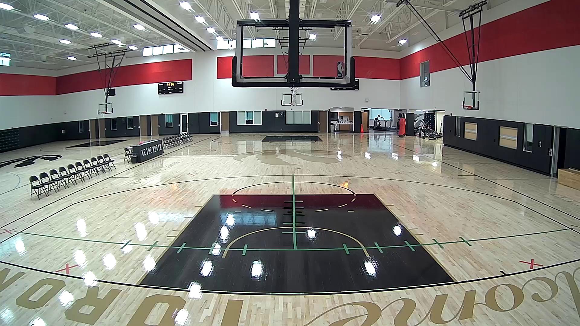
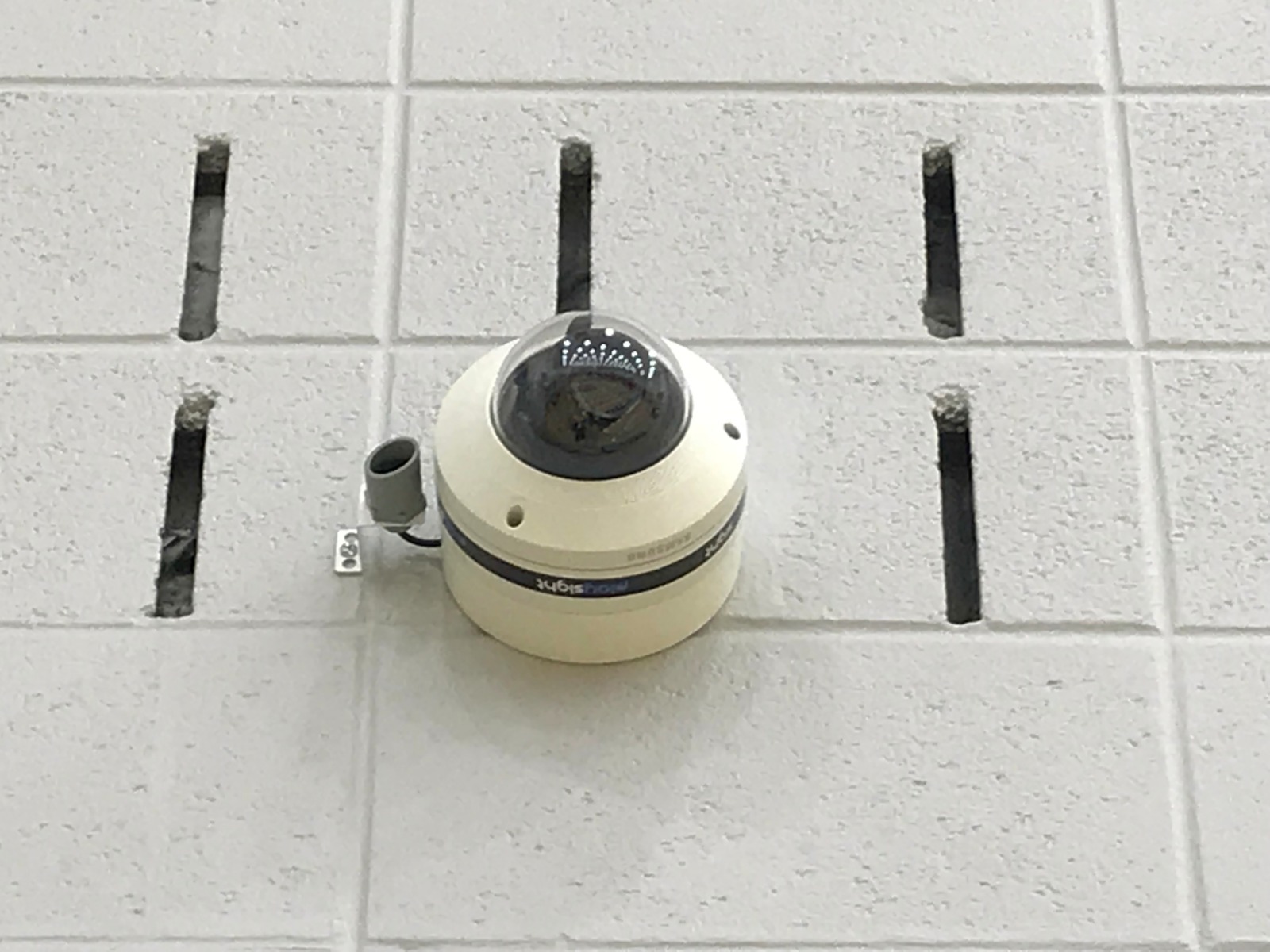
- Ideal camera location : 16-30 feet from baseline and 10-16 feet from the ground.
NOTE: Please refer to Positioning And mounting the cameras for ideal camera installation.
Official Camera Datasheet
2.Setting up your facility - Network Requirements
| Prepare | Description |
|---|---|
| Power | 110v220v AC power outlets near the location of the server |
| Lighting | On the day of installation, turn ON the lights (like on a game day). |
| infrastructure – Cables requirements: | Minimum cabling requirement is CAT6A Shielded for all non-tracking cameras, and Cat7 SFTP for all SmartTracking cameras – no exceptions. The PlaySight system requires female shielded jacks on both ends. A short patch cable should be used on both ends as well to connect to cameras and switch. |
| Internet and network requirements | internet speed: minimum requirements: 5 Mb/s download and 5 Mb/s upload internet connection.
network access The PlaySight video server comes with predefined security policies; therefore, no need to configure or add it to your Domain User Settings. Whitelist all outbound HTTP/HTTPS traffic to *.playsight.com* |
| VLAN requirements | PlaySight recommends placement of the Playsight Video Server on a separate VLAN. * PlaySight IP cameras should also be on separate VLAN (same as Playsight Video Server) or should have a direct physical connection to the PlaySight server. * If separate VLAN cannot be arranged, the cameras should be wired home run from camera to Playsight Video Server and connected to the secondary NIC available on the playsight video server, making the cameras private and excluded from the client’s network. * The VLAN should provide a 100% quality network with the required bandwidth for each PlaySight IP camera: * Each 1080p camera requires 10 Mbps. * Each 4K camera requires 40 Mbps. * Each 8k camera requires 80 Mbps. |
| Live Streaming & Broadcast requirements | *The broadcast stream should support the required upload speed: * Each Streaming camera requires 5Mb/s upload to provide a good quality stream. * Using a hard-line Ethernet connection for streaming events is ideal, as Wi-Fi Internet connection is less stable than a physical connection resulting in optional streaming interruption and the viewer will be affected hardly.* 4G hotspots or any other cellular connection is even less stable than a Wi-Fi or hard-lined connection. Based on your location, and the number of people using the closest cellular tower, your streaming signal may be compromised. |
Open the following ports for all outbound to *.playsight.com:
| Port # | Protocol | Purpose | Application |
|---|---|---|---|
| 1935 | TCP | Video streaming | RTMP |
| 443 | TCP+UDP | Remote Management,
Connectivity to PlaySight Cloud Server |
LogMeIn Central,
PlaySight Global Comm |
| 123 | TCP+UDP | Clock synchronization | NTP-clock sync |
| 9000 | TCP | Playsight data service – Smart Court Station connection to PlaySight Cloud Server | |
| 2077
2088 |
UDP | Video streaming | ZIXI broadcaster |
| 53 | TCP+UDP | DNS Name management | |
| 1401
1402 1403 |
TCP | Score data integration tool | Sportzcast |
| 8001-8015 | TCP+UDP | Video Streaming | PSA – PlaySight Stream Accelerator |
Download full network specifications document
Tools you will need:
Tools provided by PlaySight:
- T10 Key for The Axis SmartTracker Camera
- T20 Key for other cameras if applicable (scoreboard & additional views)
Tools not provided by PlaySight:
- Drill & screws
- Ladder Lift
- mounting surfaces (wood, metal plates etc.)
- clamps
- NOTE: additional tools may be needed depending on your facility.
3.What's In The Box
A typical PlaySight crate includes:
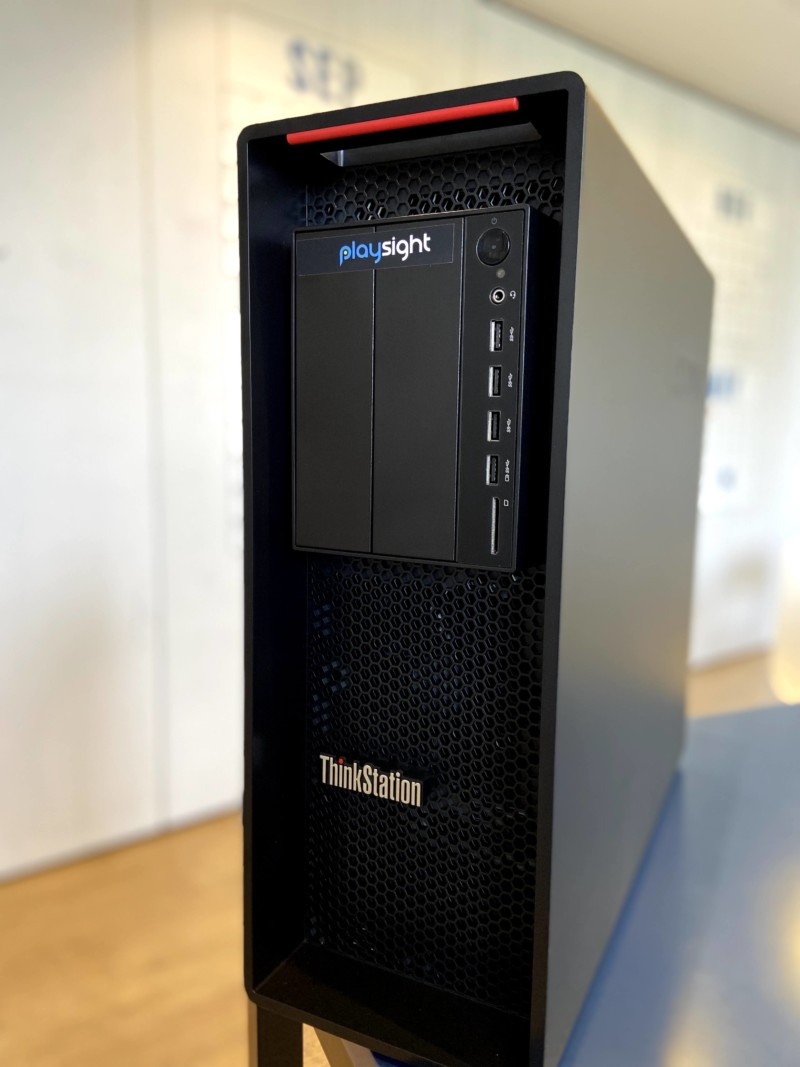
* PlaySight 4U SmartCourt Computing Unit (SCU)
* SmartTracker network camera – Axis\Hikvision
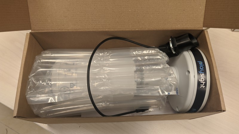
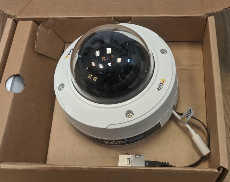
* Axis dome overview camera (P3245-LVE) + mic + mounting plate (optional)
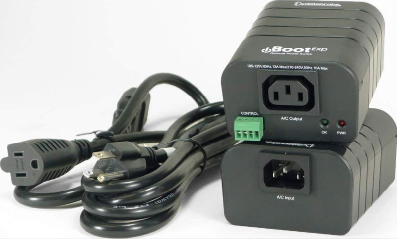
* Web power switch (iBoot)
* Energy saving surge suppressor
NOTE: items in the crate may vary according to the customer’s order
- Web Power Switch
- Axis Network Camera
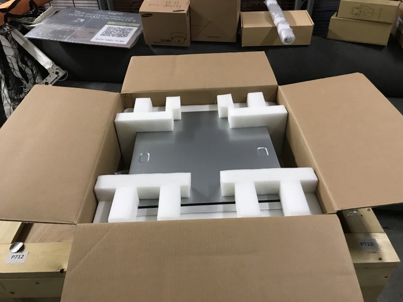
- 4U SmartCourt Computing Unit (SCU) in a box
- Axis Dome Camera (Optional)
- 4U SmartCourt Computing Unit (SCU)
5.Connecting The System
Where should you store the server?
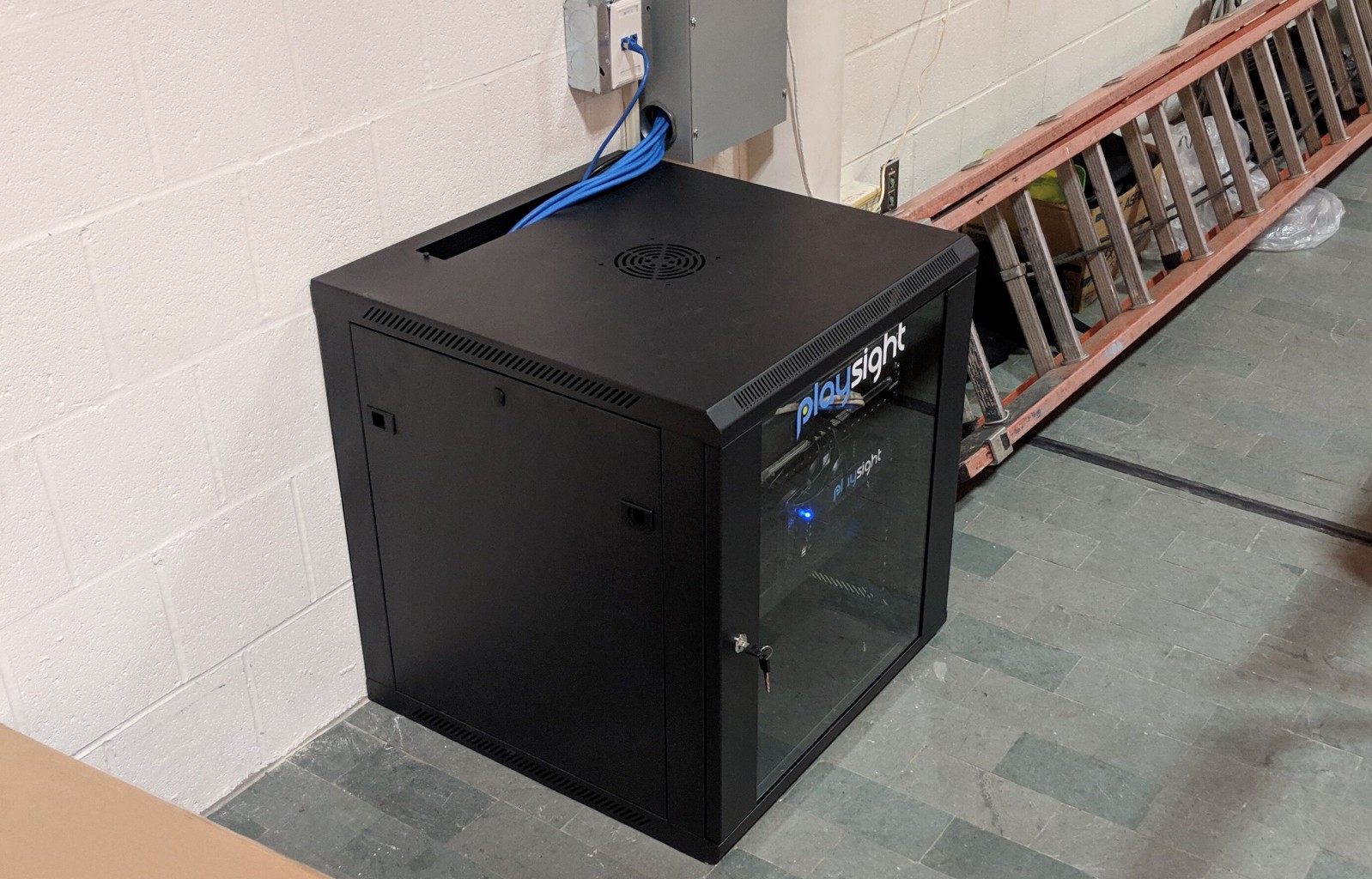
The PlaySight 4U SmartCourt Computing Unit (SCU) should be stored in your server room, or inside a corresponding server rack at a cool and dry place (not over 80F\27C).
* The Server Rack is not provided by Playsight
Lets connect!
Only proceed to this step once you have completed all the network requirements preparations and fully reviewed the system layout diagrams – you are ready to install and connect the system;
- Connect the power plug to the server (marked in green below)
- Connect the ethernet cables coming from the cameras to the patch panel – to ports 1-8 (PoE ports marked in yellow) of the NetGear switch.
- Connect an ethernet cable from the NetGear switch to the internet port on the SmartCourt computing unit (marked in blue)
- Connect an ethernet cable from the NetGear switch to the cameras port on the SmartCourt computing unit (marked in purple)
NOTE:
The cameras should be physically connected to the SmartCourt computing unit through a POE switch, meaning the cameras would be on Playsight’s own private network using the computer’s separate NIC.
Need more help? Contact support@playsight.com for further assistance.
6.Instant Replay VAR
What is the Instant Replay feature?
Instant Replay allows coaches or referees to view videos instantly without interrupting recording.
The coaches and referees can pull videos of a session currently being recorded, from the PlaySight SmartCourt Computing Unit (SCU) locally via Wi-Fi and display it on their mobile devices (iOS and Android), to show a replay of a specific move, or review a decision of the referee in previous plays.
What are the requirements for Instant Replay to function?
The Wi-Fi network used on the mobile device running the PlaySight app needs to allow a local connection from the mobile device to the PlaySight SCU via port 80, and the SSID needs to be from the same network/VLAN as the PlaySight SCU.
This Wi-Fi SSID also needs to have internet access to allow the mobile app to authenticate the user during login. A strong Wi-Fi signal is very important for optimal performance of this feature.
contact support@playsight.com and let us know which SSID you are using.
7.1.Positioning And mounting the cameras (Volleyball)
Full HD Network Camera
In order to get the best View for streaming purposes:
The camera needs to be positioned 17-80 ft. from the side-line, and at 17-30 ft. of height (see mounting guidelines below).
!!!! make or remove? !!!!
Heights and Distances Table
positioning guidelines
Streaming camera guidelines for the best view:
!!!! see if i need this !!!!
!!!! Add a VolleyBall Image from Design team (Denis) – requested already !!!!
Positioning angle camera XNV 6080
Angle cameras can be installed in addition to the SmartTracker camera, to get additional views of the action.
the side cameras can be installed anywhere (half court top view, corner view etc.)
- Side 1
- Side 2
- Side 3
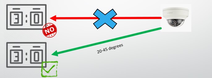
Positioning Scoreboard camera XNV 6120
* Mount the camera between 15-65ft (5-20 meters) away from the scoreboard.
* The camera must be Installed directly in front of the scoreboard.
* The camera must be 20-45 degrees higher than the scoreboard.
7.2.Mounting Dome Cameras
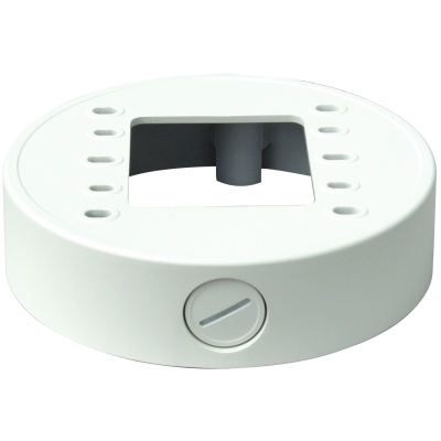
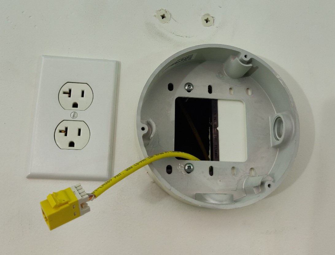
After choosing the camera placement location, mount the camera plate using 4 screws as seen below (on wall, board, rails, ceiling, designated plate or box etc.)
you can also use the accompanied black plate: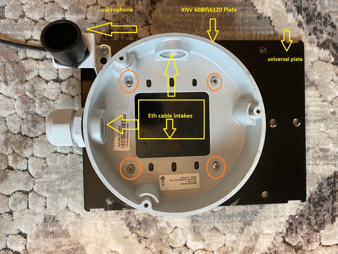
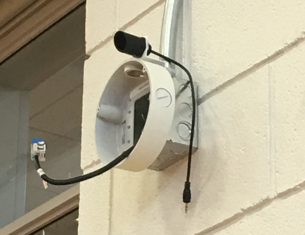
2.mount the microphone (attached with the camera) near the camera:
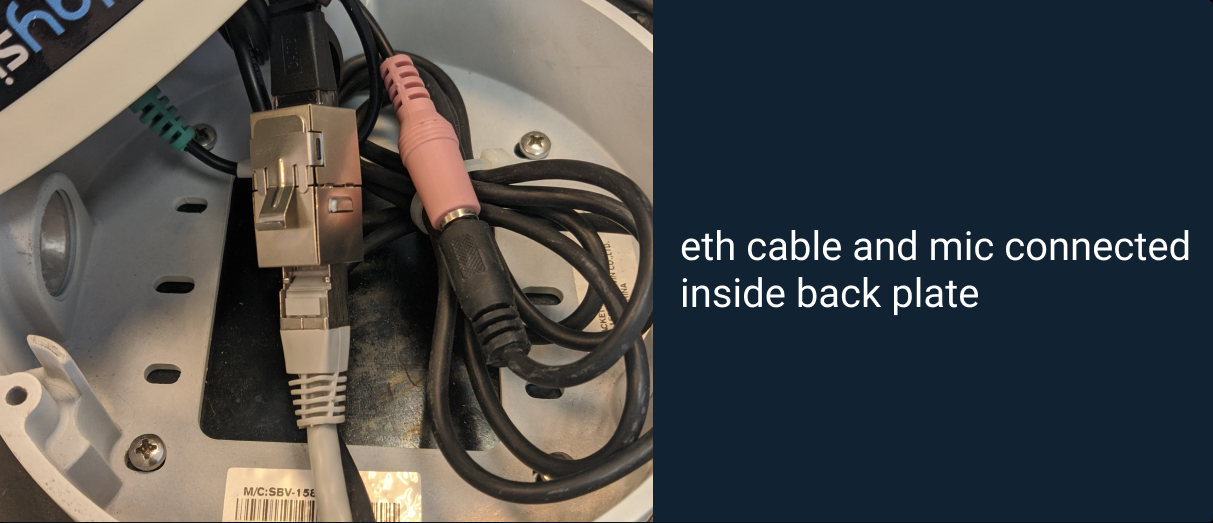
3. Make sure the eth cable+ RJ45 and microphone cables are inside the camera plate.
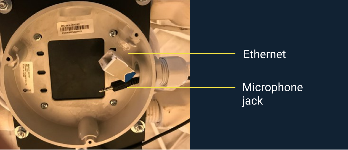
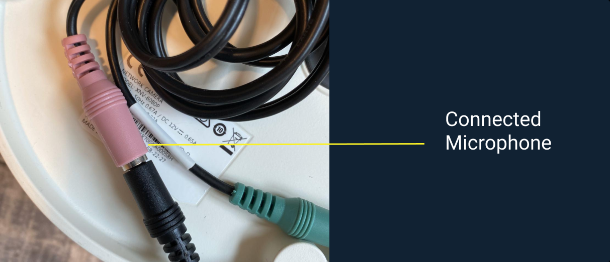
4. Connect the mic jack to the female jack of the camera (in pink)
5. Connect the eth cable to the rj45 female connector. assuming the infrastructure is complete and connected, you should see a blinking green light on the camera.
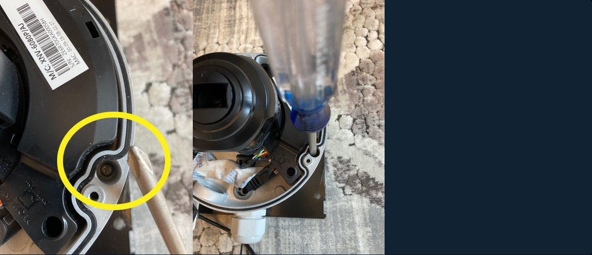
6. Place the camera on its plate and tighten using a Phillips screw driver.
7. At this stage you should see call Playsight support at support@playsight.com in order to set the zoom, focus, and wanted FOV (field of view).
8. When the FOV is set, carefully close the cover using the T20 star key:
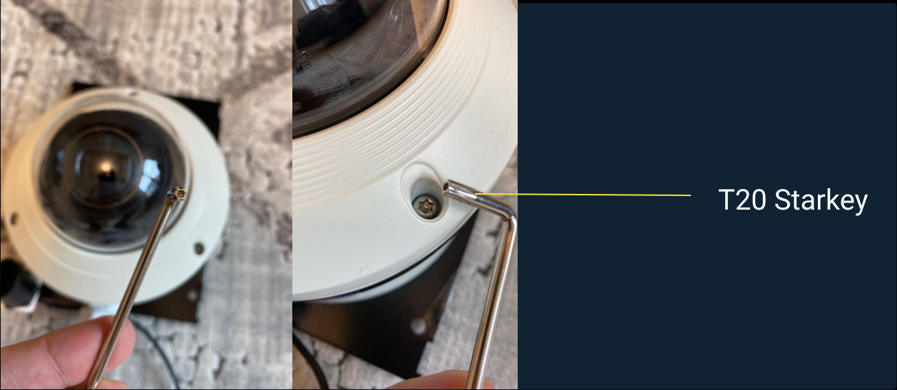
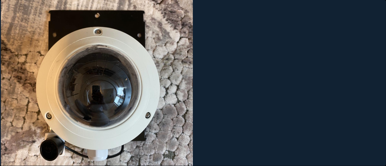
You’re have completed the camera mounting!
8.Integrations
PlaySight captures the commentator audio through the local network and embeds with the court/field audio and video for recording and streaming.
the commentary kit includes:
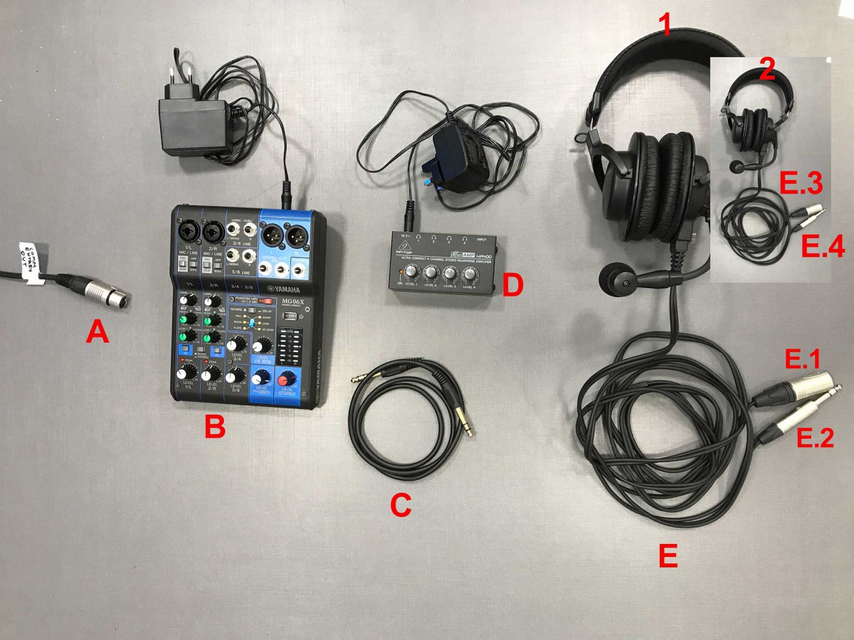
A. XLR cable connected to the Playsight mixer
B. Mixer for commentators and power cable
C. PL cable
D. Headphone Splitter for multiple commentary inputs + power cable
E. headsets
E.1 microphone output (XLR) + E.3
E.2 headphone input (PL) + E.4
how to connect:
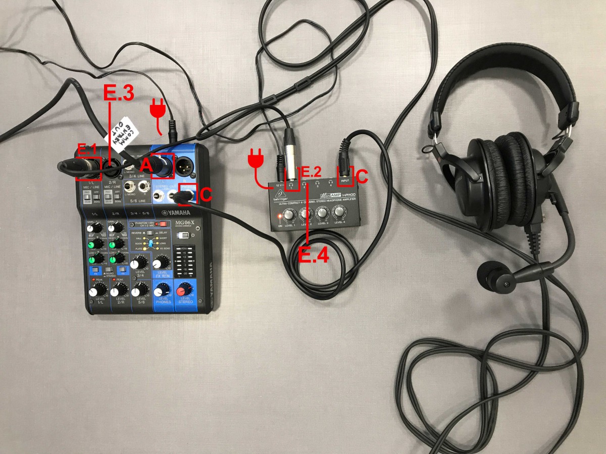
- Connect the XLR cable (A) to the STEREO OUTPUT on the mixer.
- Connect the PL cable (C) to phones on mixer.
- Connect the end-piece to the INPUT on the headphone splitter
XLR headset - Connect the XLR cable to: 1 / L MIC line on mixer
The second commentator must connect to the 2 / R MIC / LINE
PL helmet (E.2) - Connect the PL to input 1 on the headset splitter.
- Connect the mixer (B) to the power socket.
Button settings:
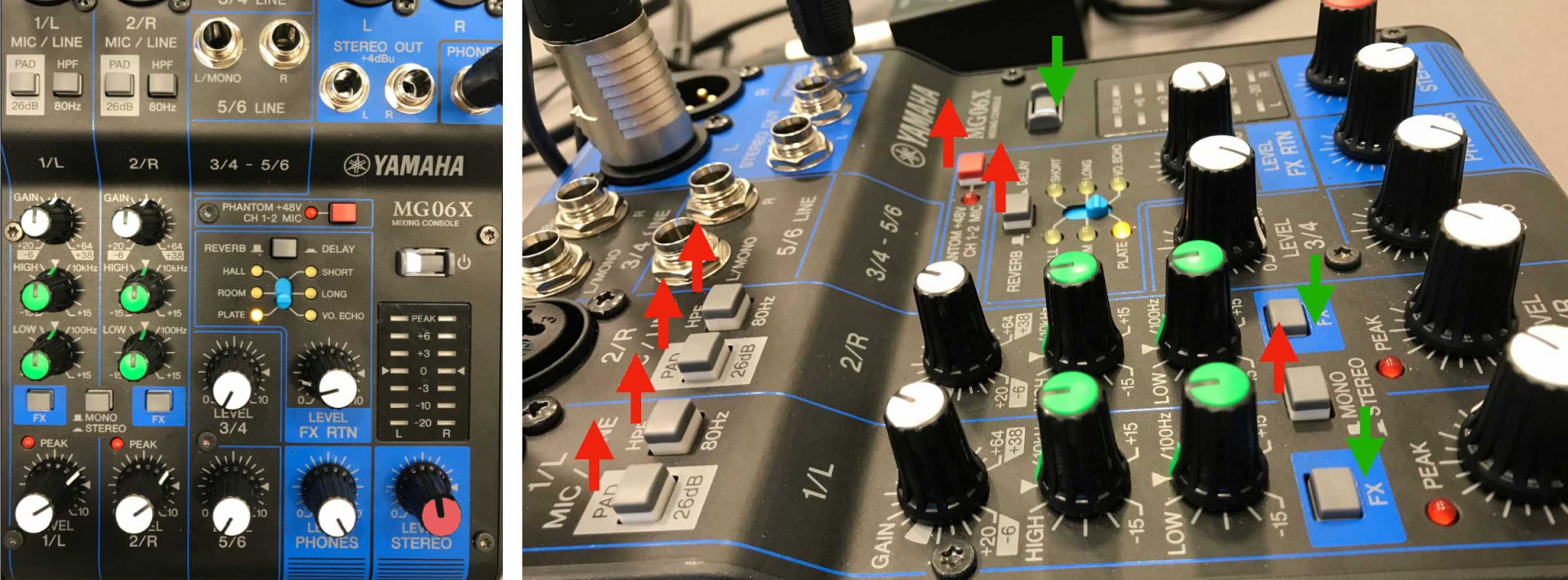
Red arrow = not active // Green arrow = active
Each button must be adjusted to the position as shown in the image on the left
NOTE:
To mute a commentator during broadcast, press the PAD button (G) (pressed button= muted, unpressed to restore sound).
Now your kit is set up, you can start commentating!
8.1.SportZcast
SportzCast
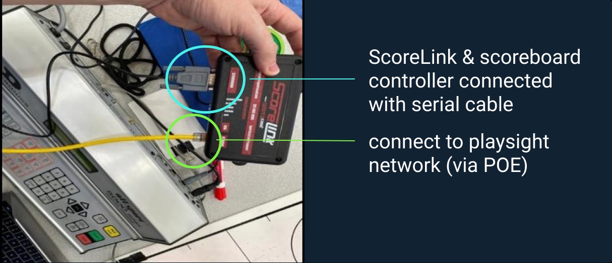
Sportzcast grabs data from the scoreboard controller, and passes it to the PlaySight SCU in real-time.
We then create a digital scoreboard overlay and embed it on the live video of the streaming camera. Based on the same data, we automatically generate events tagging in real-time, and scoreboard information is perfectly synced with the video.
Once connection and setup is completed, contact support at support@playsight.com and tell us the Serial Number of the Sportzcast unit to test the integration.
8.2.Commentating kit
PlaySight captures the commentator audio through the local network and embeds with the court/field audio and video for recording and streaming.
the commentary kit includes:

A. XLR cable connected to the Playsight mixer
B. Mixer for commentators and power cable
C. PL cable
D. Headphone Splitter for multiple commentary inputs + power cable
E. headsets
E.1 microphone output (XLR) + E.3
E.2 headphone input (PL) + E.4
how to connect:

- Connect the XLR cable (A) to the STEREO OUTPUT on the mixer.
- Connect the PL cable (C) to phones on mixer.
- Connect the end-piece to the INPUT on the headphone splitter
XLR headset - Connect the XLR cable to: 1 / L MIC line on mixer
The second commentator must connect to the 2 / R MIC / LINE
PL helmet (E.2) - Connect the PL to input 1 on the headset splitter.
- Connect the mixer (B) to the power socket.
Button settings:

Red arrow = not active // Green arrow = active
Each button must be adjusted to the position as shown in the image on the left
NOTE:
To mute a commentator during broadcast, DO NOT use the LEVEL button (F).
press the PAD button (G) (pressed button= muted, unpressed to restore sound).
Now your kit is set up, you can start commentating!
8.3.OCR Scoreboard
OCR (Optical Character Recognition):
A POE camera is installed and pointed at the scoreboard. Our system then reads data directly from the scoreboard using OCR technology to generate the same digital scoreboard overlay and event tagging capability.
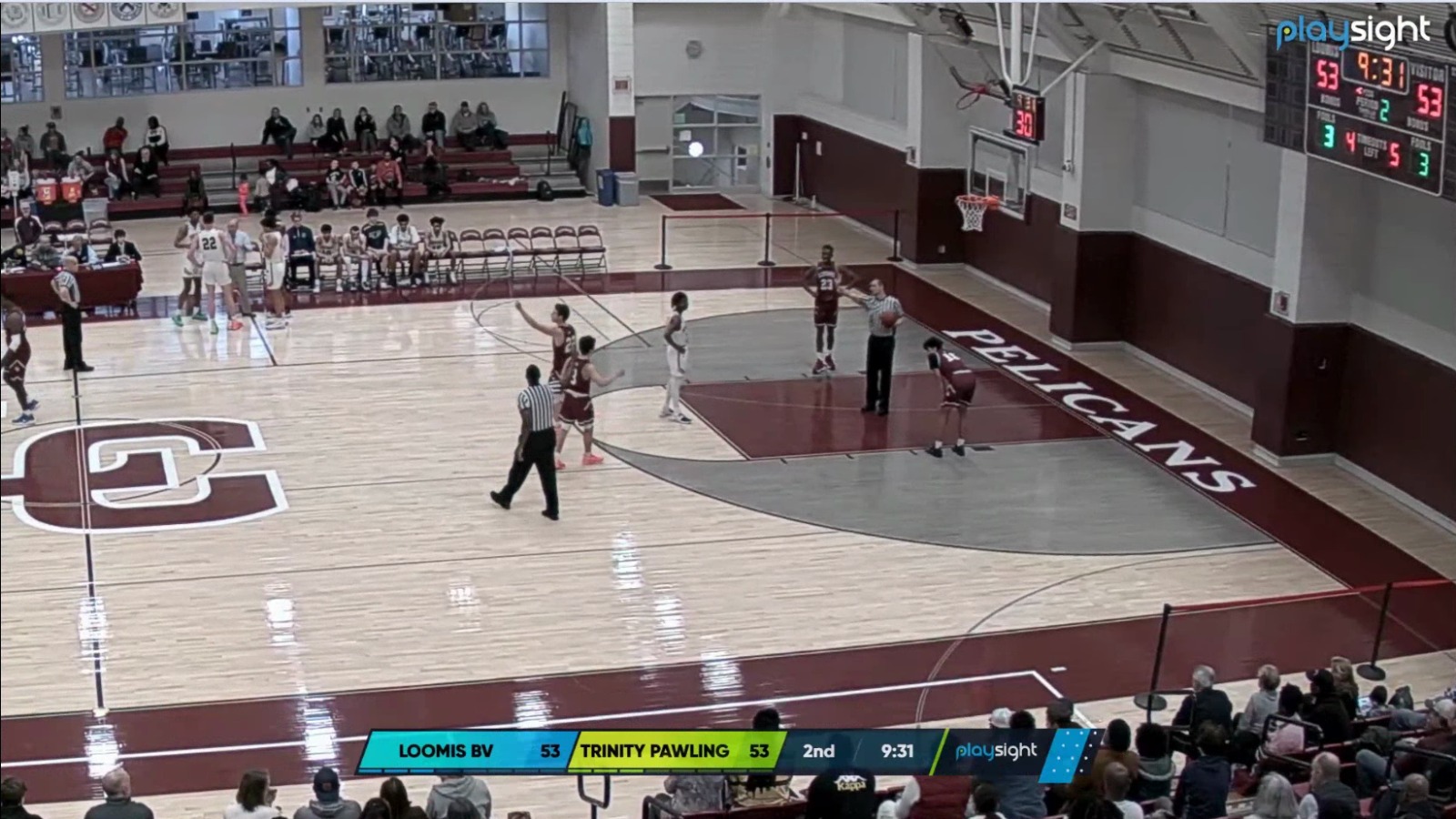
OCR Scoreboard displayed on SmartTracker video, synchronized with the real physical scoreboard.
9.Appendix
Official Camera Datasheets:
Playsight Network Requirements:
Misc:
10.Troubleshooting
Installation Process Troubleshooting:
* Computer does not turn on
1. This may be due to a power issue. Please make sure the computer is properly connected to the power source.
2. Please check if the power supply switch in the back of the computer is turned on
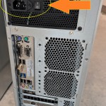
The computer should automatically start once power is restored. If this is not the case, press the Power On/Off button in the front of the computer.
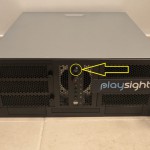
In rare cases, some internal components might come loose during shipment. If you’re comfortable, we recommend opening the computer case to make sure components inside are securely connected.
Feel free to reach out to support@playsight.com for guidance.
* Computer does not connect to the internet
- Please make sure the network connection coming from the switch/router is live and working by connecting a laptop to that line.
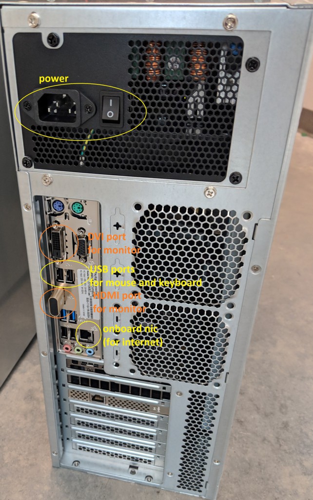
2. Please make sure the network cable is connected to the onboard network card (NIC).
-
-
-
-
- The onboard NIC comes configured to DHCP. If the computer requires static IP to get online, please follow these steps:
- Connect a monitor, mouse and keyboard to the computer
- There are USB ports in front and back of the computer for connecting the mouse and keyboard
- There are DVI and HDMI ports in the back of the computer for connecting the monitor
- Once the monitor, keyboard and mouse are connected, right click the network icon in the taskbar and select “Open Network & Internet Settings“
- Go to “Change adapter Options“
- Look for the Intel NIC, right click and select “Properties“
- Select TCP/IPv4 and click Properties
- The example above indicates the computer is set to DHCP. In order to set it to static, select “Use the following IP address” then enter the IP address, Subnet mask, and Gateway needed, and apply changes. If the computer still does not connect to the internet, please reach out to your network administrator.
- Connect a monitor, mouse and keyboard to the computer
- The onboard NIC comes configured to DHCP. If the computer requires static IP to get online, please follow these steps:
-
-
-
Commentating kit:
- I wear the headset but I can’t hear myself nor the other commentator:
– Make sure the mixer (B) is connected and activated.
– Make sure the headphone divider is plugged in and charged.
– Make sure the mixer (B) and the headphones are connected to the PL cable.
– Make sure that the PL helmet is connected to the helmet divider and that the Level button is activated.
– Make sure that the LEVEL 1 / L and LEVEL 2 / R buttons on the mixer are activated. - I can hear myself but the recording or the transmission does not work
– Ensure that the XLR (A) is connected to the Playsight mixer server.
– Make sure that the two buttons (LINE and PAD) are not pressed.
feel free to reach out to support@playsight.com for further assistance.

